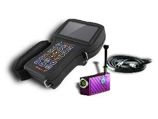
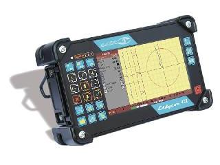
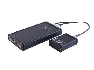
The Eddycon C portable eddy current flaw detectors is powerful NDT tools for a wide range of applications in aerospace, railway, power generation, petrochemical, and heavy machinery industries.
Retaining the best characteristics of their predecessors, the Eddycon C features a user-friendly intuitive interface, which creates a smooth workflow, and a high- resolution TFT colour display.
Also you may watch the Eddycon C Training video set. See more

The device is intended for the detection of surface breaking defects, detection of subsurface defects (cracks, overlaps, holes, fine cracks, etc.) in non-ferrous conductive materials, inspection of bolt holes with rotary scanners, as well as measurement of coating thickness, electrical conductivity, weld testing and magnetic permeability.
The Eddycon C strictly complies with the ISO 15548 requirements.
The instrument allows full eddy current testing of aircraft parts according to the regulations of AIRBUS A318 / A319 / A320 / A321 NONDESTRUCTIVE TESTING MANUAL NTM, BOEING 737 NON-DESTRUCTIVE TEST MANUAL.
Key Features:
- Simplicity of operation due to the user-friendly interface;
- Sound and light alarm functions;
- Possibility of avoiding the influence of lift-off noise and inhomogeneity of electromagnetic properties;
- Extensive data storage;
- Data transmission to a PC via USB flash drive or Ethernet.
- Reviewing test results and printing out test reports;
- Easy download of software upgrade via USB flash drives.
- Defect depth evaluation capability;
- Reviewing indications on the flaw detector;
- -20°C to +50°C operating temperature range;
- Continuous 8-hour operation with a quick-release rechargeable battery;
- Small size and light weight – up to 2 lbs (0.9 kg).
Ergonomic Design
The Eddycon C enables one-handed operation with an easy thumb access to all the keys. The side strap secures the device firmly yet comfortably in the inspector’s hand, and light weight allows performing inspections for a long period of time without getting tired.


High-Resolution Display
4.3" TFT color display with 800×480 pixels resolution provides high visibility in any lighting conditions. The screen offers several display modes, such as light, dark, and standard.
GET A QUICK QUOTE FROM US TODAY
REQUEST A QUOTEDifferent modes of full-screen presentation

a) Menu+XY+A(t)

b) Menu+XY

c) Menu+A(t)

d) XY+A(t)

e) XY

f) A(t)
Navigation
Elaborated keypad design gives a quick access to any menu of the flaw detector by pressing a single key only!
TESTING menu - main operating mode of the flaw detector;
MEMORY menu - is used to save/download the settings and test results;
SETTINGS menu - basic settings of the flaw detector;
VIEW menu - allows viewing test results saved to the flaw detector’s memory;
CALIBRATION menu - serves to create calibration curves for more precise evaluation of flaw depth.

Industrial applications:
eddy current crack detection of railway parts and car units (wheelsets and axle box bogies of freight, refrigerator and passenger cars, automatic coupler, etc.).
eddy current inspection of aircraft engineering parts (wheel disks, skin, turbine blades, multi-layered structures, various holes, etc.).
examination of pipelines, industrial tanks, etc.
eddy current crack detection of pipelines, turbine blades of gas-distributing stations (GDS), pressure vessels, etc.
non-destructive testing of steam generator tubes and headers by eddy current bobbin probes, etc.
eddy current inspection of bars, wires, steel structures, mill rollers, plates, etc.
Eddycon is now available in two versions

Specialized application-dependent software of the Eddycon C multipurpose eddy current flaw detector serves for processing test results, as well as generating and printing out test reports. The software program allows working with the data saved on PC.
Main advantages of the program are as follows:
- Intuitive user-friendly interface.
- Easy viewing of test results for each frequency mode (Frequency №1, Frequency №2 & Mix).
- Generation and storage of electronic reports.
- Data output for each detected flaw, namely:
- flaw location coordinate on a defectogram (if using an encoder);
- signal amplitude and phase;
- flaw depth.
The resulting electronic report contains all basic data on test performed, such as:
- Company name, NDT department and inspector who performed the test.
- Description of a test object.
- All setting parameters of the instrument at the time of testing.
- Parameters of signals coming from defects (amplitude, phase, depth).
- Representation of the signals from defects in a complex plane or strip chart).
- Inspection date.
- Possibility to create reports of other types, when approved by the customer.

| Housing | |
| Overall dimensions | 9.5" × 4.4" × 5.3" (241 mm × 112 mm × 135 mm) |
| Weight | up to 2 lbs (0.9 kg) |
| Applicable standards | СЕ, ISO 15548 |
| Supply mains | 100 V to 240 V, 50 Hz - 60 Hz |
| Inputs & outputs | 2.0 USB-port (hub), Ethernet (Lemo 4-way), headphones (Lemo 4-way) |
| Keypad | American, International (icons) |
| Operation conditions | |
| Operation temperature | -4 to +122° F (-20 to +50°C) |
| Storage temperature | -4 to +122° F (-20 to +50°C) |
| IP rating | IP 64 |
| Battery | |
| Type | Li-Ion 12V/4500 mA·h |
| Operation time | Normal mode — up to 7 hours; If using rotary scanners — 4 to 5 hours |
| Display | |
| Display size | 4.3" |
| Type | Color TFT (800×480 pixels) |
| Display modes | Normal, full-screen; three color schemes |
| Grid | Three types: coarse, fine, polar |
| Connectivity and data storage | |
| PC software | Test results processing program |
| Data storage | MicroSD 4 Gb internal memory card (up to 64 Gb as an option); |
| ET specifications | |
| Frequency range | 10 Hz to 16 MHz |
| Gain | 70 dB |
| Probe supply voltage | 0.5 V; 1V; 2V; 4V; 6V |
| Additional gain | 30 dB |
| Phase rotation | 0 to 359.9 |
| Digital scale | 1/16 to 16, with a step of 6 dB |
| Test frequency | 1 to 11 kHz |
| Signal indication time | 0.1 s; 0.3 s; 0.5 s; 1 s; 2 s; 3 s; 4 s; 5 s; 8 s |
| Filter | Low-pass: 1 to 5 000 Hz High-pass: 1 to 5 000 Hz Bandpass Averaging Differential |
| Connected probes | Single, Reflection, Bridge |
| Probe connector | Lemo 00, Lemo 12-way / Lemo 16-way |
| Signal display modes | Complex plane – X(y); Time base – X(t), Y(t); Dual-frequency mode |
| Threshold level types | Circle, Threshold, Sector, Trapezium |
| Multi-frequency operation | Dual-frequency multiplexing; Independent control of both frequencies; Mix of two frequencies (F1 - F2, F1 + F2) |
| Eddy current flaw detector Eddycon C (Lemo 16) |
| Eddy current probe SS340K09DA0 |
| Connection cable Lemo 16 – Lemo 04 (connector type 0В, Reflection type) |
| Charger Mascot Type 2542 |
| Calibration block RS 2353/1-3N-Fe |
| Software for operation with PC |
| Operating Manual EC.14327992.02.13 OM |
| Quick start guide |
| Operating Manual Mascot 2542 |
| Registration certificate for reference standard RS 2353/1-3N-Fe |
| Case |
| Bag |
| Registration certificate for ECP |
| Eddy current flaw detector Eddycon C (Lemo 12) |
| Eddy current probe SS340K09DA0 |
| Connection cable Lemo 12 – Lemo 04 (connector type 0В, Reflection type) |
| Charger Mascot Type 2542 |
| Calibration block RS 2353/1-3N-Fe |
| Software for operation with PC |
| Operating Manual EC.14327992.02.13 OM |
| Quick start guide |
| Operating Manual Mascot 2542 |
| Registration certificate for reference standard RS 2353/1-3N-Fe |
| Case |
| Bag |
| Registration certificate for ECP |
| № | Description | Notes |
| CABLES | ||
| 1.1 | Connecting cable Lemo 16 – Lemo 16 (for rotary scanner SVR-05), 70 in. | For rotary scanners |
| 1.2 | Connecting cable Lemo 16 – Lemo 04 (for Reflection type probes), 70 in. | For Lemo 4-way probes (EGG.0B) |
| 1.3 | Connecting cable Lemo 16 – Lemo 04 (for Bridge type probess), 70 in. | |
| 1.4 | Connecting cable Lemo 16 – Lemo Triax (for Reflection type probes), 70 in. | For Lemo Triax probes (ERN.0S650.CTA) |
| 1.5 | Connecting cable Lemo 16 – Lemo Triax (for Bridge type probes), 70 in. | |
| 1.6 | Connecting cable Lemo 16 – Lemo 04 (for Conductivity probes), 47 in. | For CP-13 (conductivity probe) |
| 1.7 | Connecting cable Lemo 00 – Microdot/М5 (for single coil probes), 70 in. | For probes with Microdot connector |
| ROTARY SCANNERS | ||
| 2.1 | Rotary scanner SVR-05 | Lemo 16-way connector |
| BATTERY | ||
| 3.1 | Replaceable battery pack | |
| 3.2 | Adapter for charging the replaceable battery pack | |
| № | Description | Notes |
| CABLES | ||
| 1.1 | Connecting cable Lemo 12 – Lemo 12 (for rotary scanner SVR-04), 70 in. | For rotary scanners |
| 1.2 | Connecting cable Lemo 12 – Lemo 04 (for Reflection type probes), 70 in. | For Lemo 4-way probes (EGG.0B) |
| 1.3 | Connecting cable Lemo 12 – Lemo 04 (for Bridge type probes), 70 in. | |
| 1.4 | Connecting cable Lemo 12 – Lemo Triax (for Reflection type probes), 70 in. | For Lemo Triax probes (ERN.0S650.CTA) |
| 1.5 | Connecting cable Lemo 12 – Lemo Triax (for Bridge type probes), 70 in. | |
| 1.6 | Connecting cable Lemo 12 – Lemo 04 (for Conductivity probes), 47 in. | For CP-13 (conductivity probe) |
| 1.7 | Connecting cable Lemo 00 – Microdot/М5 (for single coil probes), 70 in. | For probes with Microdot connector |
| ROTARY SCANNERS | ||
| 2.1 | Rotary scanner SVR-04 | Lemo 12-way connector |
| BATTERY | ||
| 3.1 | Replaceable battery pack | |
| 3.2 | Adapter for charging the replaceable battery pack | |
Instructional Video
Should you have any questions, feel free to contact us


