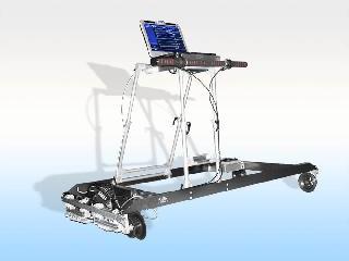
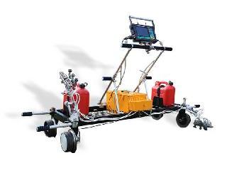
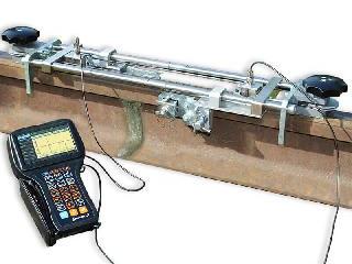
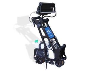
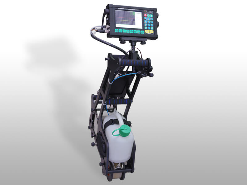
Ultrasonic single-rail flaw detector UDS2-77 SC is a manually driven cart designed for autonomous inspection of one streetcar line with rails of "groove" type and standard profile rails during .
Qualitative 100% control of the rail is provided at a scanning speed of up to 5 km/h, which corresponds to the average walking speed of a person.
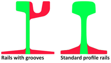
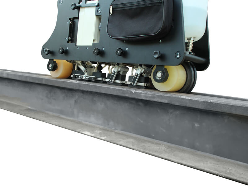
The rail flaw detector uses a unique scanning scheme that allows you to control the entire section of the rail, with the exception of the sole flanges and the groove limiter, using the pulse-echo, echo-shadow and echo-image methods.
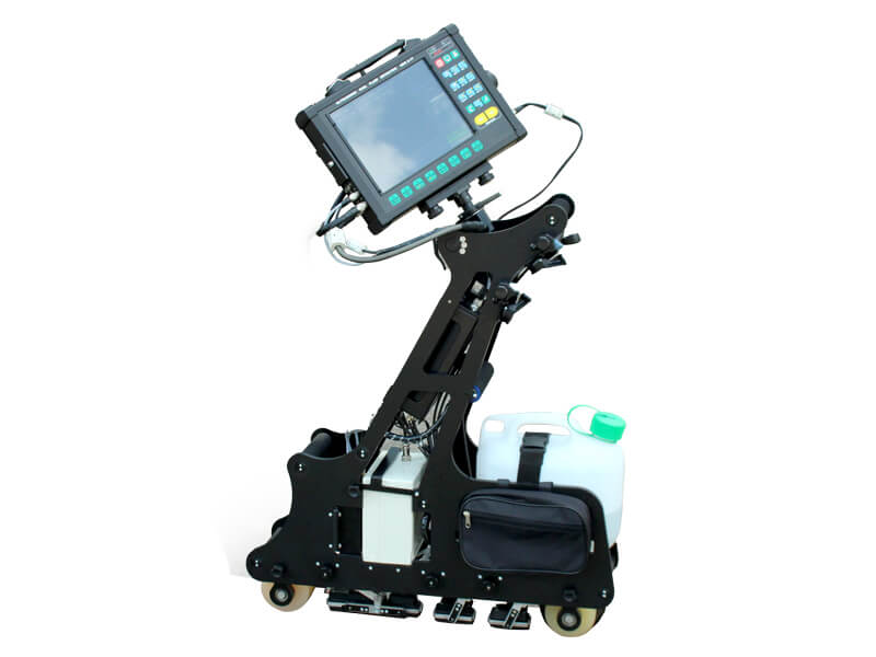
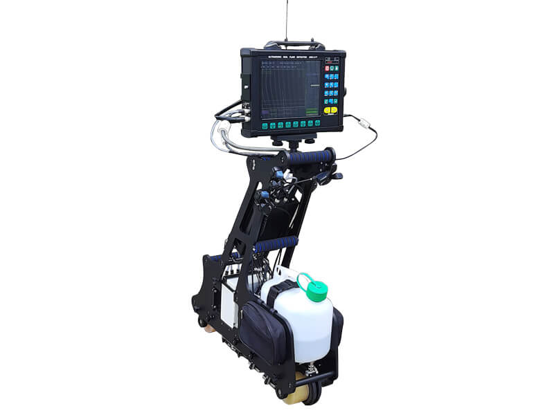
Trolley design
- Modular design of the trolley consists of a support frame with adaptive rollers; electronic unit for control and visualization; multichannel unit; battery pack; couplant (water) tank; probe units; suspension mechanism of the probe units to place them into operation/transportation position; encoder.
- Position of electronic unit for control and visualization can be adjusted along three axes.
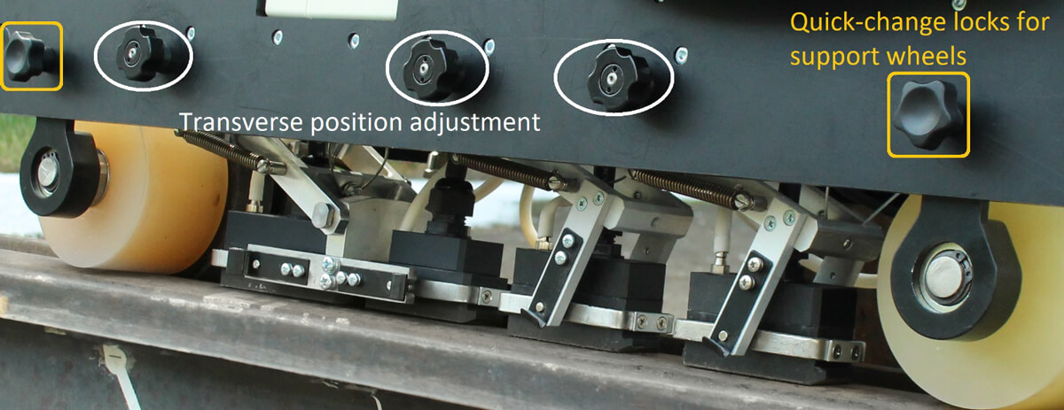
- Probe unit (slide or roller) is transversely positioned in relation to a rail with the help of a dedicated control device.
- The probe unit (slide or roller) is positioned cross-wise to the rail with the aid of a dedicated control device
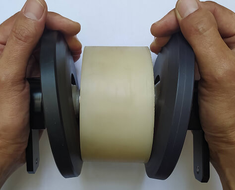
- Probe unit can be centered using adaptive rollers.
- Suspension mechanism of the slide probe unit ensures a stable acoustic contact.
- The electronic equipment of the flaw detector is resistant to moisture, dust and corrosion. The protection class is not less than IP54 according to EN60529.
The trolley is made of lightweight but rigid composite materials, bringing the total weight of the device to no more than 20.5 kg. (without water and GPS/Wi-Fi module). The total weight of the flaw detector with couplant and GPS/Wi-Fi module is no more than 26.5 kg.
Some original technical solutions for the UDS2-77 SC design centering and adjustment systems make it possible to test with a single flaw detector a plurality of rails of the same type but different in geometry and dimensions
The design of support rollers for rails with a groove and tram rails of a standard profile has dynamic adaptive elements in its design, which always ensures the location of the scanning unit's initial adjustment selected by the operator during in subsequent control.
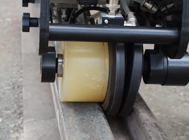
The location of the scanning units on the surface of the rail head has a transverse adjustment. The transverse adjustment provides adjustment of the scanning units for successful ultrasonic testing of any rail sizes and any degree of wear (permissible by standards).
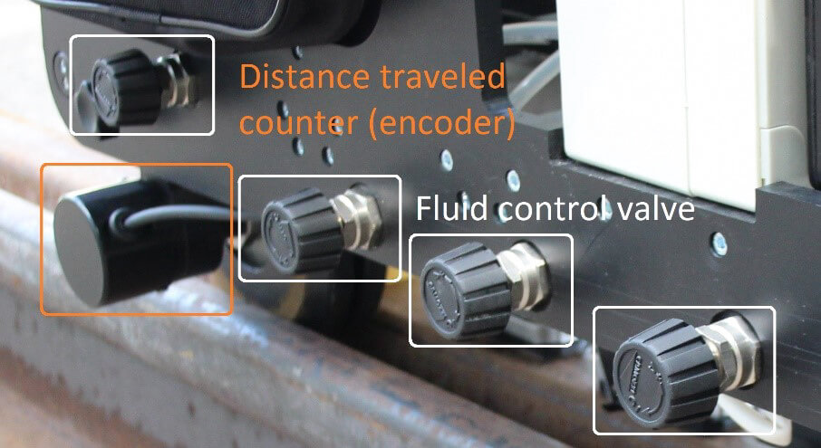
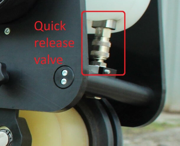
Each probe unit has its own (independent) contact fluid system with a fluid control valve. For quick and easy contact fluid refilling, the tank can be unbolted and installed without fluid loss thanks to a quick-release valve with automatic safety lock. The average fluid consumption is 1 liter per 1 kilometer of control.
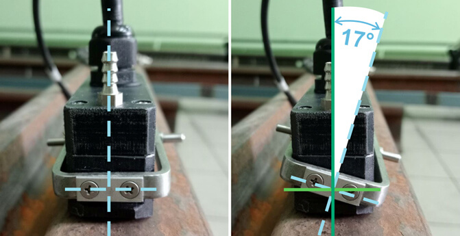
Each sensor unit has its own (independent) suspension system and transverse angular degrees of freedom, which ensures constant acoustic contact when the flaw detector operator deviates from the rail vertically within 17 degrees both to the left and to the right.
Each probe unit hanger has a separate mechanism for moving the Probe Unit to the transport position. With the help of these mechanisms, it is possible to weaken or increase the clamping force of each block. In the transport position or move the blocks in the transport position, the probe unit is raised 20 mm above the rail head.

Using GPS/Wi-Fi module in addition to the track coordinate, geolocation coordinates can be additionally recorded, which facilitates identification of the defective section of the railroad track. Also, when the operator forms all available types of reports, the geolocation coordinate is automatically entered into the reports. A total of 7 types of reports are available: 3 operational reports at the detection site using a flaw detector and 4 types of reports in the post-processing mode using a special, pre-installed software "RailInspector".
Key features
- Scanning the rail in one pass in one direction;
- Detection of artificial reflectors in the form of flat-bottom holes and cylindrical holes according to EN 16729-1;
- The step of sounding the rail at a testing speed of up to 5 km/h is no more than 2,5 mm;
- Representation of test results in the form of A-scan, multi-A-scan, B-scan for all channels;
- Real-time display of test results in the form of B-scan;
- Data recording and saving (operator’s name, line, direction, track number, left/right position, initial track coordinate, date, time, final track coordinate);
- Screenshot saving (PrintScreen);
- Saving of test results in the form of data array (B-scan) to the internal memory;
- Use of USB flash drive for transmitting the test results to PC;
- Saving track coordinate (Encoder) and global coordinate (GPS);
- Availability of measuring gates in A-scan & B-scan modes;
- Post-viewing of test result on the flaw detector with the possibility to measure conditional sizes of defects;
- Possibility to put the track markers (e.g. “Bridge”, “Crossing”, “Bolt hole”, etc.).
- Signaling about the presence of defects: sound, light, visual, indication of the set testing sensitivity values, defect coordinates, current track coordinate - digital on the screen built into the flaw detector.
The flaw detector provides detection of internal defects in streetcar rails in accordance with the following codes per IRS 70712:2018 (UIC 712 R):
- HORIZONTAL CRACKING OF THE RAIL HEAD – code 112 (0°probe – pulse echo and echo-images technique);
- VERTICAL CRACKING OF THE RAIL HEAD – code 113 (0° probe – pulse echo and echo-images technique, and 45°probe – pulse echo technique, in case of the crack location in the web projection);
- SHELLING OF RUNNING SURFACE – code 122 (0° probe – pulse echo technique);
- HORIZONTAL CRACKING AT THE WEB-HEAD FILLET RADIUS – code 1321(2321) (0° probe – pulse echo and echo-images technique);
- HORIZONTAL CRACKING AT THE WEB-FOOT FILLET RADIUS – code 1322 (2322) (0° probe – pulse echo and echo-images technique);
- LONGITUDINAL VERTICAL CRACKING (PIPING) – code 133 (233) (0° probe – pulse echo and echo-images technique, 45° probe – pulse echo technique);
- STAR-CRACKING OF FISHBOLT HOLES – code 135 (235) (0°probe – pulse echo and echo-images technique, 45° probe – pulse echo technique);
- DIAGONAL CRACKING AWAY FROM ANY HOLE – code 236 (0°probe – 45°probe);
- PROGRESSIVE TRANSVERSE CRACKING (KIDNEY-SHAPED FATIGUE CRACK) – code 211 (70° probe, 55° probe – pulse echo and echo-mirror technique ‘Rhomb’);
- HORIZONTAL CRACKING – code 212 (0° probe – pulse echo and echo-images technique, 45° probe – pulse echo technique);
- LONGITUDINAL VERTICAL CRACK – code 213 (0° probe, pulse echo and echo- images technique, 45°probe – pulse echo technique, in case of the crack location in the web projection);
- SHELLING OF THE RUNNING SURFACE – code 2221 (0° probe – pulse echo and echo-images technique);
- SHELLING OF THE GAUGE CORNER – code 2222 (55°probe – pulse echo technique);
- HEAD CHECKING / FISSURING / SCALING AT THE GAUGE CORNER – code 2223 (55° probe – pulse echo technique, 70° probe, displaced into the gauge face side)
- ISOLATED WHEEL BURN – code 2251 (0° probe, 55° probe – echo-mirror technique ‘Rhomb’);
- REPEATED WHEEL BURNS – code 2252 (0°probe, 55° probe – echo-mirror technique ‘Rhomb’);
- SQUAT / CRACKING AND LOCAL DEPRESSION OF THE RUNNING SURFACE – code 227 (0 probe, 55° probe – echo-mirror technique ‘Rhomb’, 70°probe);
- LONGITUDINAL VERTICAL CRACKING – code 253 (0° probe – echo-images technique, in case of the crack location in the web projection);
- CORROSION – code 254.2 (45° probe – pulse echo technique);
- FAULTY MACHINING – code 302 (70°probe, 55° probe – pulse echo, echo-mirror technique);
- TRANSVERSE CRACKING OF THE PROFILE – code 411 (421, 431) (70°probe, 55° probe – pulse echo, echo-mirror technique);
- HORIZONTAL CRACKING OF THE WEB – code 412 (422, 432) (0° probe, 45°probe);
- TRANSVERSE CRACKING OF THE RAIL HEAD – code 471 (70°probe, 58° probe – pulse echo, echo-mirror technique, 45°probe);
- DETACHMENT OR SHELLING OF THE RESURFACED PORTION – code 472 (0°probe);
- TRANSVERSE CRACKING UNDER ELECTRICAL CONNECTION – code 481 (0°probe, 70°probe, 58° probe – pulse echo, echo-mirror technique, 45° probe).
Functionality ultrasonic electronic equipment of a single rail flaw detector UDS2-77 SC
- ADC discretization frequency - at least 60 MHz;
Recording of testing results in online mode for at least 50 km of the traveled distance.
- Display of testing results in the form of A-scan and B-scan in real time in the following modes:
- Simultaneous display of testing results in the form of A-scan and B-scan on one selected channel.
- Simultaneous display of testing results as a B-scan on all channels.
- Display of testing results in the form of A-scan by the selected channel.
- Displaying testing results as multi-A-scan.
- Testing registration mode, which includes filling in the following fields:
- Date and time of testing (saved automatically when initializing testing results).
- Line number (filled in manually by the operator or selected from the list).
- Rail (selected manually by the operator).
- Race number (name) (filled in manually by the operator or selected from the list).
- Number (name) of the operator (filled in manually by the operator or selected from the list).
- Number of the flaw detector (saved automatically).
- Gain of each ultrasound channel (saved automatically).
- testing direction (selected manually by the operator)
- Rail: left/right
- Basic data of the defect description: line number, track number, track (or global) coordinates of the defect, type of defect according to the "UIC 712 R" catalog.
- The time of continuous operation of the flaw detector from a fully charged battery is at least 12 hours.
- Availability of two strobes with selection of ASD operating modes (for Echo or EIT methods).
- It is possible to disable/enable the sound alarm for each strobe separately.
- Availability of sound and visual (LED and segmental on-screen) signaling when the threshold level signal is crossed.
- Ability to adjust gain in the range from 0 to 80 dB.
- Ability to adjust gain in steps of 0.5, 1, 10 dB.
It is constructing the HRC curve separately for each ultrasound channel.
- The dynamic range of HF is not less than 70 dB.
- The number of VRC points is at least 14.
- Presence of a screen (LCD) 10'' with high resolution for high-quality display of testing results in the form of B-scan with color amplitude gradation;
- The presence of a sun-protective hood during the monitoring of sunny weather.
- The flaw detector during operation is resistant to the action of the following climatic factors: ambient air temperature from minus 30 to plus 55°C and air humidity 95%;
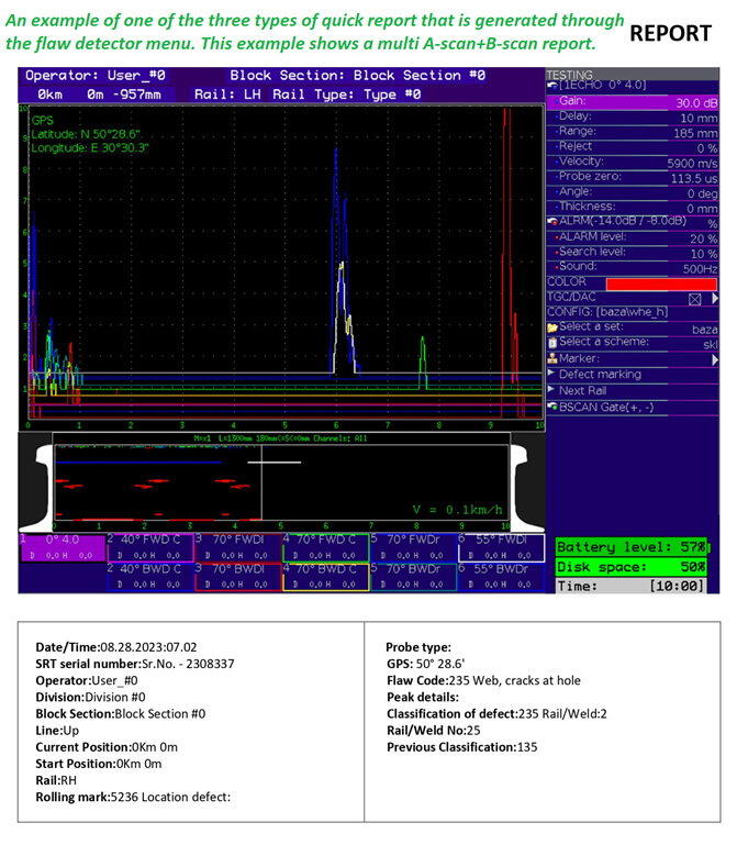
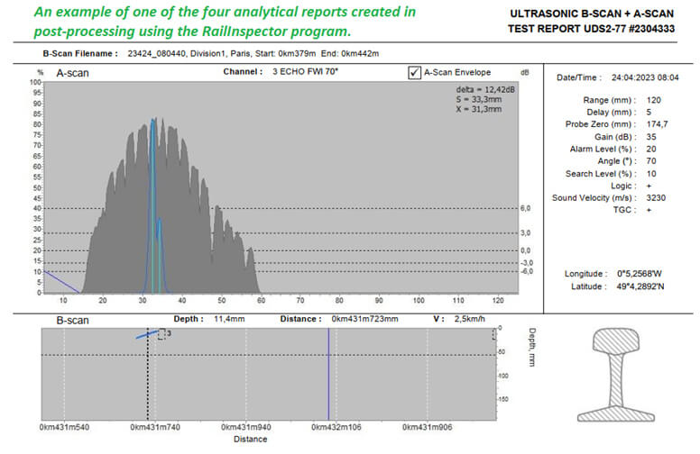
REPORTS
The user has access to 3 types of quick reports generated from the device menu, as well as 4 analytical reports that are generated on a remote workstation on a computer using special software "RailInspector"
In any of these reports, the descriptive part of the registered defect parameters contains the following basic information:
- track and global coordinate of the defect (saved automatically);
- defect number according to the catalog (entered manually by the operator);
- the length of the defect (saved automatically during B-scan measurement or entered manually by the operator during visual inspection);
- features of the rail (filled in manually by the operator);
- The type of rail according to the marking (for example: S60, S49 or others; entered manually by the operator);
- Type of rails according to manufacturing technology (U – hardened; S – raw; C – cold drawn; manually entered by the operator or selected from the list);
- comments (filled in manually by the operator);
The UDS2-77 features a simple menu structure for setup and calibration, as well as setting of software functions/modes. The device is furnished with the Hot Keys panel to get an immediate access to main operation modes, such as display (А-scan/B-scan), correction of track coordinate, generation of test report, On/Off button for test result saving mode.
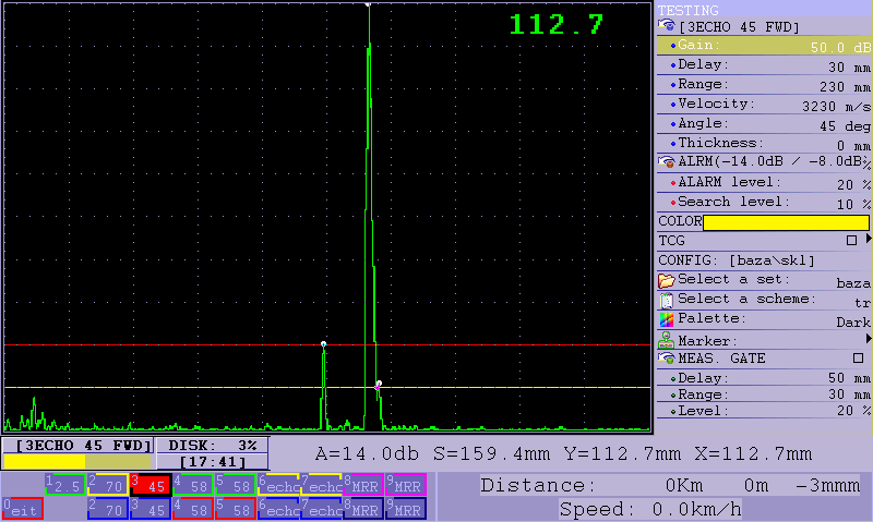
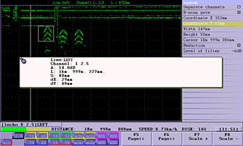
а) A-scan
b) Multi-A-scan (Indian version)
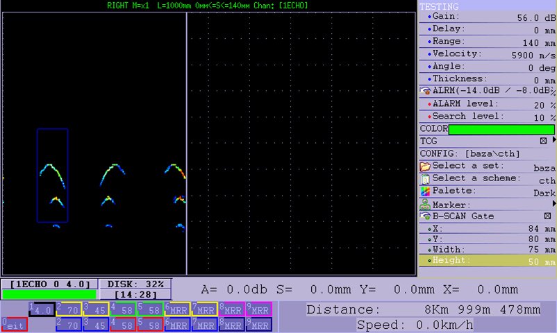
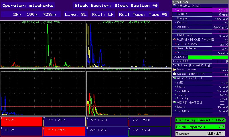
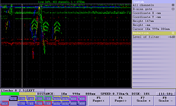
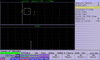
c) B-scan (all channels)
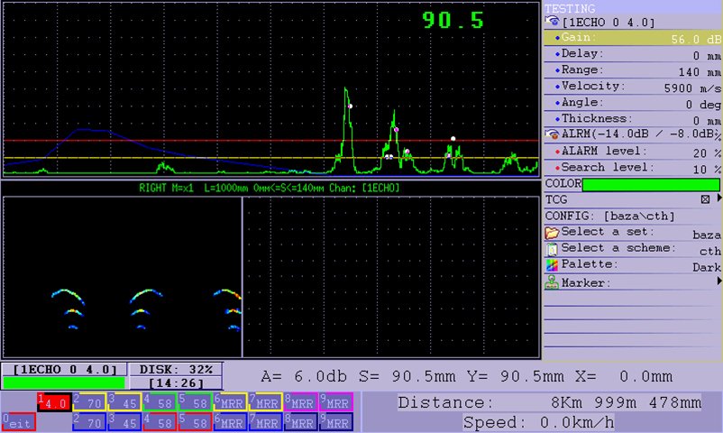
d) A-scan + B-scan
Fig. 6 — Test result display modes:
Test result post-viewing mode
a) Viewing the general menu
b) Measuring flaw parameters
c) Viewing B-scan + A-scan
Fig. 7 — Test result viewing mode
UT techniques: pulse echo, (echo image) and echo shadow.
Number of ultrasonic channels for 100% scanning: 11.
Nominal test frequency: 1 to 6 MHz.
Distance between probe pulse sendings: 2,5 mm at motion speed up to 5 km/h.
Variation range of receiving path gain: 0 to 100 dB, with a step of 1 dB.
Memory capacity for data storage: not less than 16 Gb.
Weight of the flaw detector without couplant: up to 20,5 kg.
The flaw detector is powered by an independent power source (battery) with the rated voltage 12V and rated capacity of no less than 18 А·h.
Time of operating mode setup: up to 15 sec.
Time of continuous operation of the flaw detector with a fully-charged battery: no less than 8 hours.
Protection rating: IP 64.
The following alarms are generated during flaw detection: light – common via all test channels; sound – common for a group of channels; visual, on the screen – separate for every channel.
GPS system is used to determine defect location coordinates on the track.
| № | Description | Q,ty, pcs. | Notes |
|---|---|---|---|
1 | Trolley | 1 pc. |
|
2 | Guide wheels for symmetrical (standard) rail profile. | 2 pcs. | Guide wheels for rail with groove are installed on the flaw detector by default. |
3 | System of couplant supply to probes, including:
| 1 set |
|
4 | External Loudspeaker | 1 pc. |
|
5 | Electronic unit (EU) | 1 pc. |
|
6 | Multiplexer Unit (MUX, with BNC connectors) | 2 pc. |
|
7 | Battery unit (BU) | 1 pc. |
|
8 | GPS module (Detection and fixing of defect coordinates with display in the inspection results) | 1 pc. | Optional. Not included in the base kit price. |
9 | Cable set:
| 1 set. |
|
10 | Encoder | 1 pc. |
|
11 | System of rising/lowering of probe unit (controls lever) | 3 pc. |
|
12 | Probe Unit #1:
| 1 set. |
|
13 | Probe Unit #2:
| 1 set. | Probes with an input angle of 55 degrees are not used when inspecting rails with grooves.
|
14 | Probe Unit #3: 2.0 MHz angle-beam (70°) single element probe – 2 pc; | 1 set. |
|
15 | Probe Unit #4 2.0 MHz angle-beam (70°) single element probe – 2 pc. | 1 set. | Not used when inspecting rails with grooves. |
16 | Calibration block “Rail specific gain calibration block” | 1 pc. |
|
17 | Manual probes:
| 1 set. |
|
18 | Charger | 1 pc. |
|
19 | USB-flash card | 1 pc. | Set of technical and operational documentation |
20 | Tool kit for service of the flaw detector | 1 pc. |
|
21 | Carrying and storage case with lodgment | 1 pc. |
|
22 | Protection cover for screen | 1 pc. |
|
23 | Sun hood | 1 pc. |
|
24 | Spare parts and accessories:
| 1 set. |
|
25 | Spare set of ultrasonic units
|
| Optional. Not included in the base kit price. |
26 | Operating documentation:
| 1 set |
|
27 | Calibration certificate | 1 pc | Optional. Not included in the base kit price. |