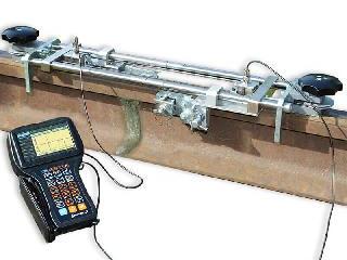
TOFD 2.2 PRO Ultrasonic Weld Testing System
The TOFD 2.2 PRO System is intended for mechanized ultrasonic butt weld inspection applying the advanced technique of Time-Of-Flight Diffraction (TOFD). Fast and reliable, the technique proves highly effective at both locating and sizing discontinuities in welds. TOFD ensures perfect accuracy of greater than ±1mm in measuring the critical through-wall size of crack-like defects in a broad range of material thickness.
The TOFD 2.2 PRO System is utilized for testing of welded joints in:
- flat objects;
- tubes of medium and large diameters – with OD no less than 12 in (300 mm) – depending on the scanner type;
- spherical and cylindrical oil and gas tanks – with OD no less than 33 ft (10 m).
Wall thickness: varying from .25 to 12 in (6 to 300 mm).
Profile types: CRC Evans, single J groove weld, single V groove weld, double V groove weld, X welds, etc.
High-Performing
The TOFD 2.2 PRO System delivers rapid full volume inspection done in a single run, providing straightaway results with data recording and imaging.
The setup time is reduced due to the element libraries: Geometry Library, Material Library, Scanner Library, Probe Library, etc.
Reliable
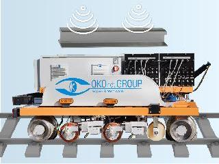
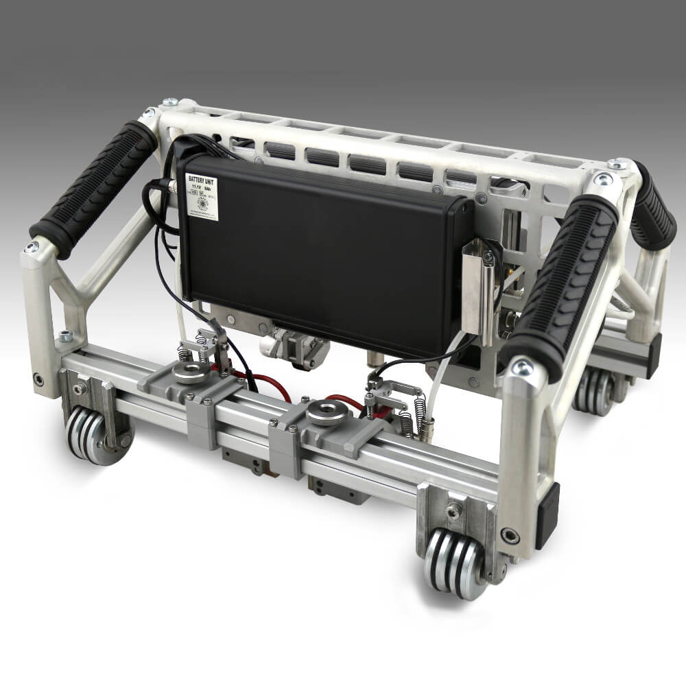
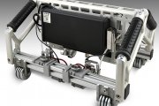
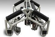
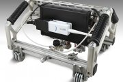
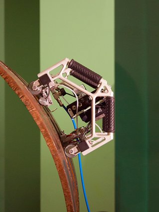
Magnetic wheels and spring loaded probe carriers with self-positioning system ensure transducer stability on the object surface which results in good coupling necessary for reliable test results.
Continuous water supply under each probe guarantees good acoustical contact.
Perfectly Suited to Demanding NDT Applications
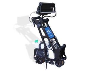
The scanner is easy to drive and doesn’t fall from the object even when upside-down.
The TOFD 2.2 PRO System boasts drop-resistant design ensuring that at fall down, the main impact will come to the scanner structure elements saving its electronics.
The TOFD 2.2 PRO System is capable of an 8-hour continuous operation on a storage battery, and it takes only several seconds to replace the battery with one hand if necessary.
The System is IP65 rated.
User-Friendly
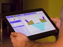
The wireless operating technology allows the NDT inspector with a data acquisition PC to stay anywhere within Wi-Fi range.
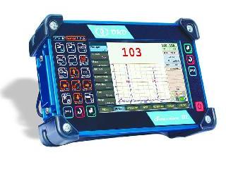
The TOFD 2.2 PRO System is compatible with any type of Windows-based computer: laptop, desktop, tablet, etc.
The interface is mouse- and finger-friendly.
Main Benefits of the TOFD Technique Application:
- flaw detection not depending on their orientation;
- detection of planar defects and cracks not perpendicular to the inspected surface;
- reproducibility of inspection;
- accurate defect positioning and sizing capability;
- amplitude insensitivity (acoustical coupling less critical);
- a cost effective solution.
Main software functions are distributed among the following tabs:
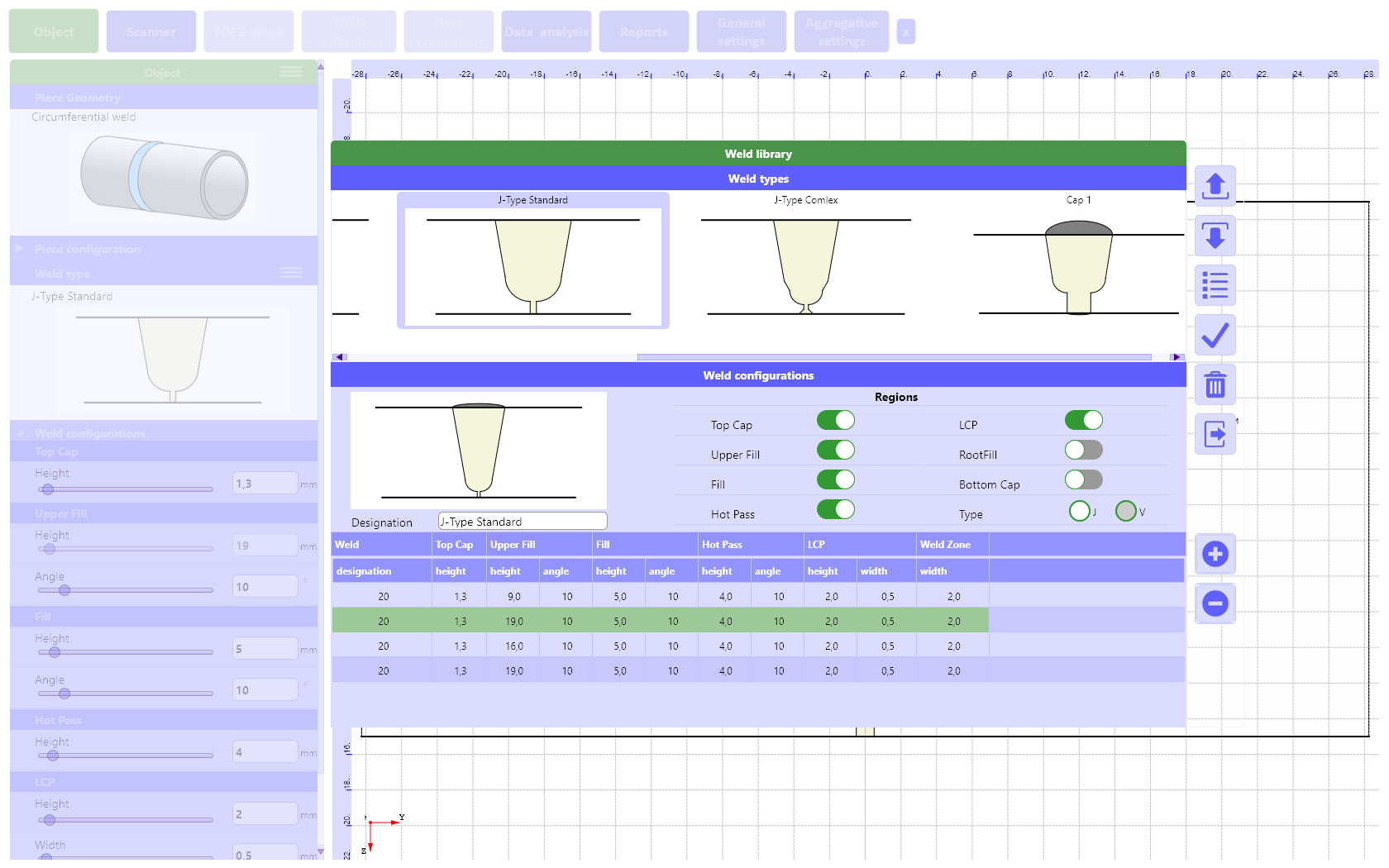
«Object» tab:
- selecting the test object geometry and setting up its dimensions;
- selecting the test object material;
- selecting the type of a weld bevel and setting up all its dimensions.
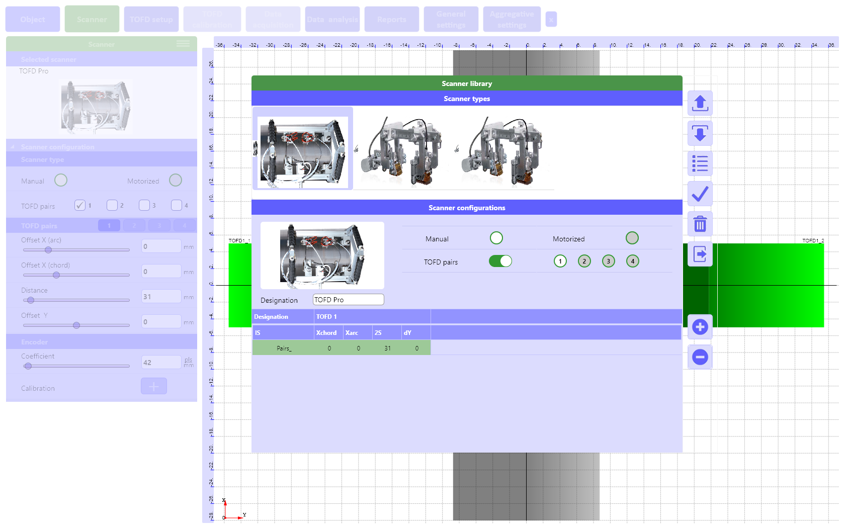
«Scanner» tab:
- selecting the scanner;
- setting up the scanner type: manual, motor-operated;
- setting up the spatial position of TOFD transducers pairs relative to the origin of the coordinate system;
- using of up to 4 TOFD transducer pairs;
- carrying out encoder calibration.
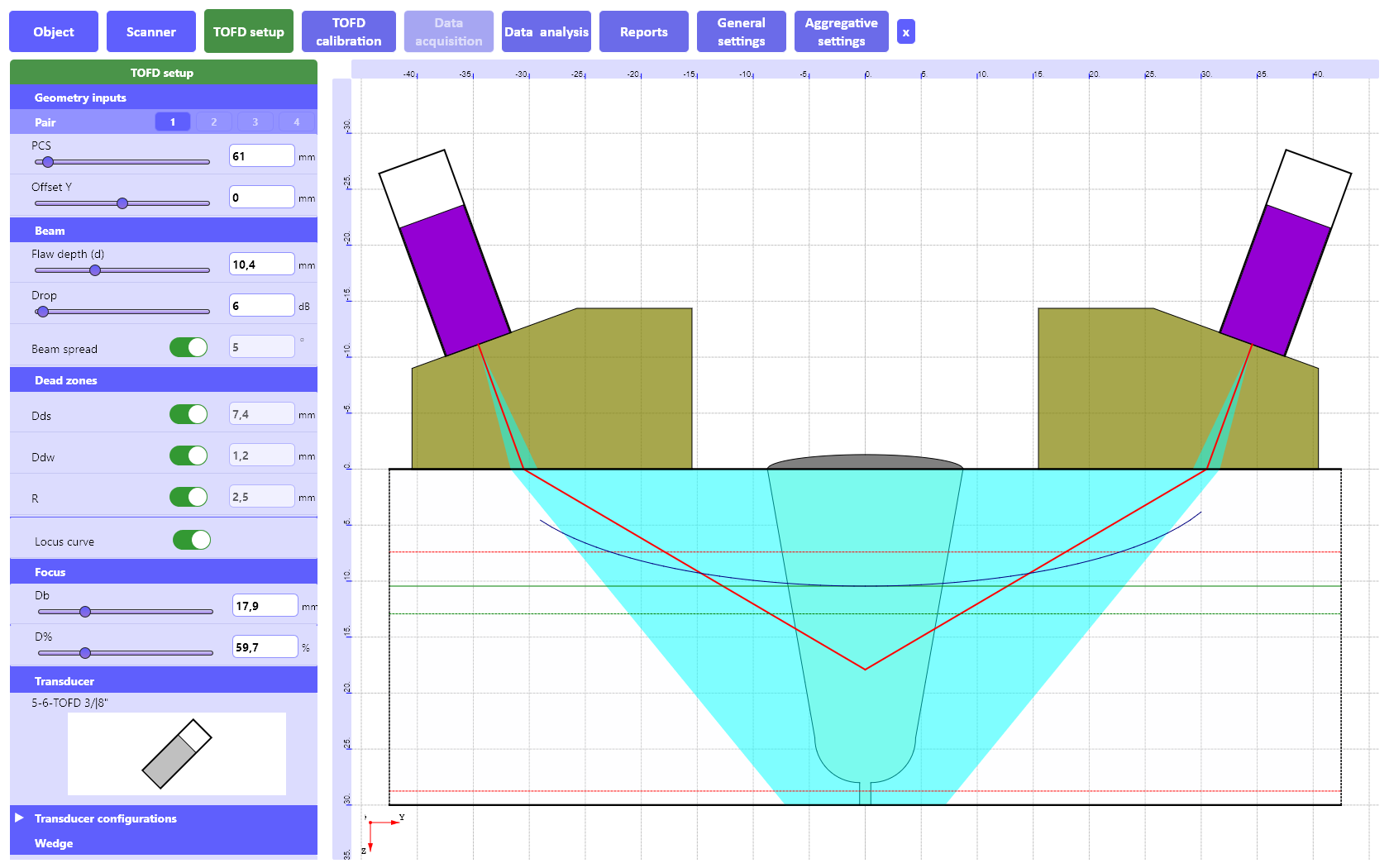
«TOFD setup» tab:
- selecting the type of TOFD probes, TOFD wedges, or setup of their parameters;
- setting up the PCS – the distance between the index points of TOFD transducers and their shift relative to the welded joint axis;
- calculation and graphic display of the following parameters using TOFD Calculator:
- Spatial resolution (R);
- Scanning-surface dead zone (D);
- Backwall dead zone (D);
- Locus curve;
- Beam Spread.
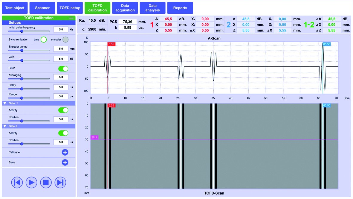
«TOFD Calibration» tab:
- setting up the main UT parameters;
- carrying out the real-time TOFD calibration;
- real-time checkup of reflectors detection in calibration block;
- saving the calibration results.
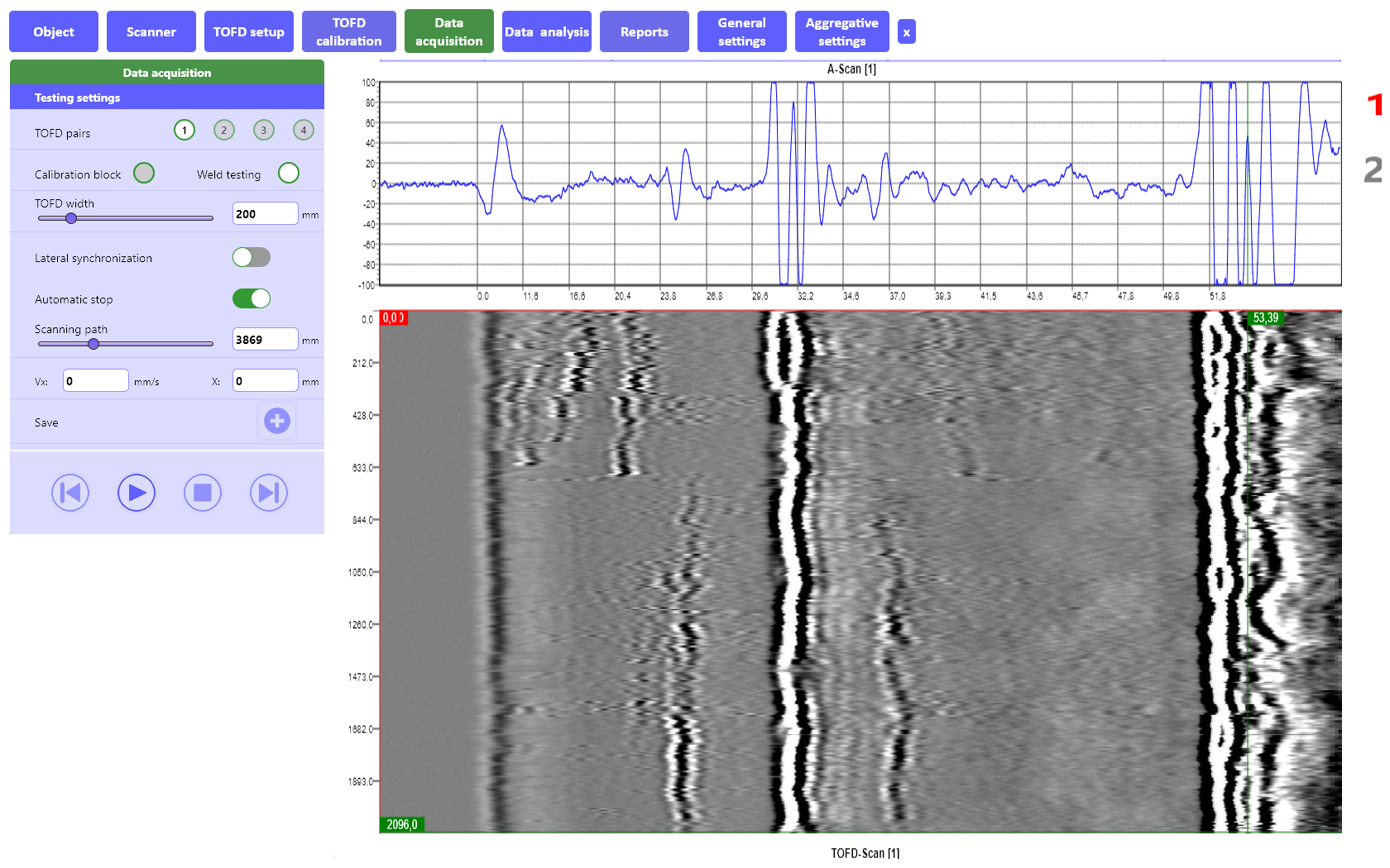
«Data acquisition» tab:
- A-Scan + TOFD-Scan display during the testing process;
- carrying out the testing and data acquisition;
- displaying the current scanner position and the scanning speed;
- data synchronization by lateral wave during the testing process;
- considering the scanning direction and capability to rescan the regions with the acoustic coupling loss;
- saving the testing results.
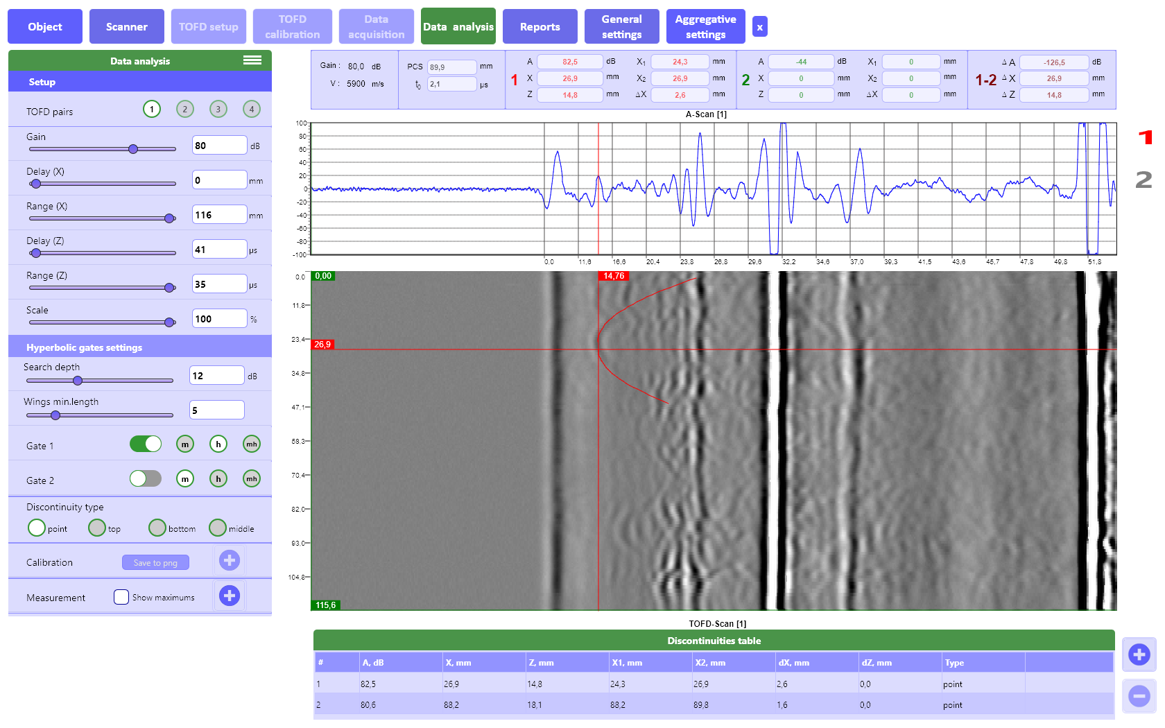
«Data analysis» tab:
- review and analysis of saved data in a form of А-Scans and TOFD-Scans;
- quick and detailed analysis of testing results using two measuring gates (type: normal, hyperbolic, manual hyperbolic);
- for all indications, the following parameters can be measured:
- their position in the object (X and Y-coordinates);
- their length (ΔX);
- their depth and height (Z, ΔZ);
- their type: “volumetric”, ˝top-surface breaking˝, ˝bottom-surface breaking˝ or ˝inner˝;
- building the defects table and its saving.
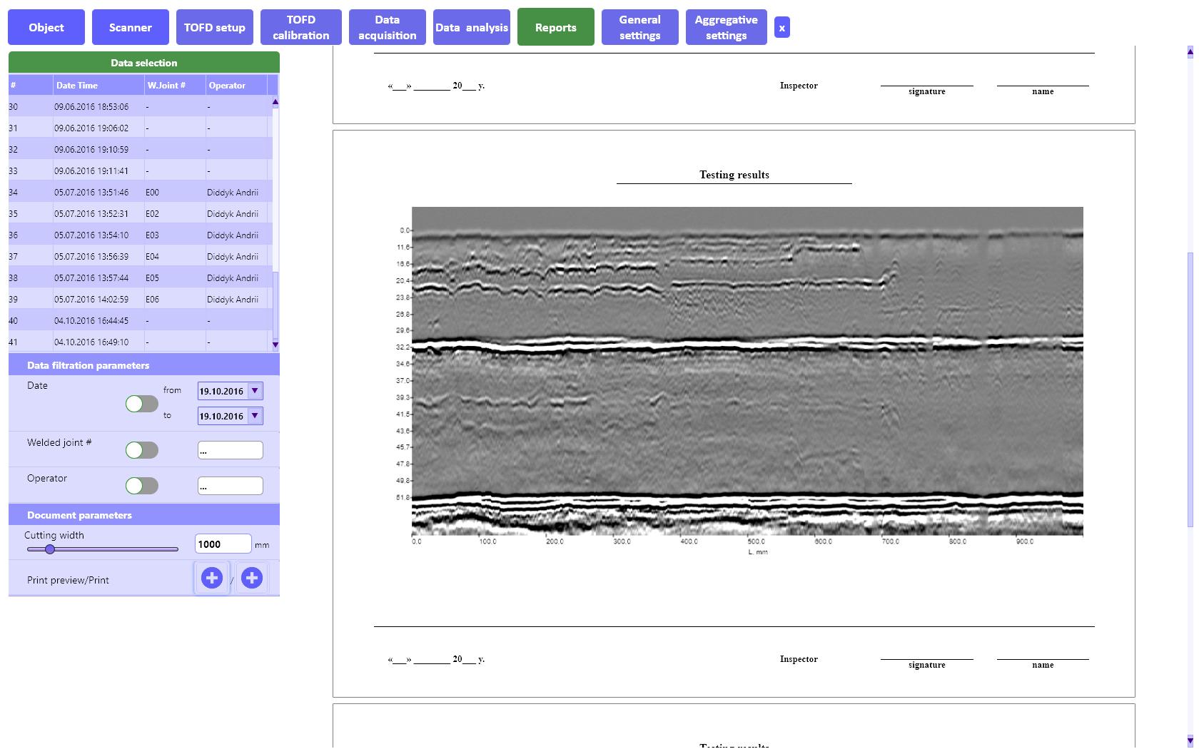
«Reports» tab:
- Sorting and filtering of testing results in the database;
- TOFD scan scaling for printout;
- Reports preview;
- Reports printing.
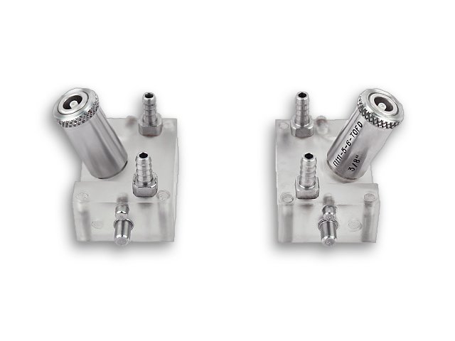
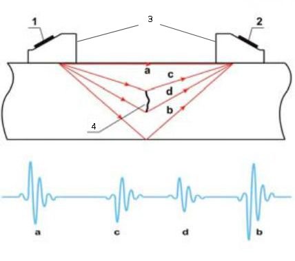
- Transmitter;
- Receiver;
- Wedges;
- Internal crack.
- lateral wave;
- back wall echo;
- diffracted signal from the top tip;
- diffracted signal from the bottom tip.
TOFD transducers specification:
| Catalog number | Frequency, MHz | Element dia. | Object thickness | ||
| in | mm | in | mm | ||
| TWS10-3-TOFD 3/8" | 10 | .125 | 3 | .390-.600 | 10-15 |
| TWS10-6-TOFD 3/8" | 10 | .250 | 6 | .600-1.4 | 15-35 |
| * TWS5-6-TOFD 3/8" | 5 | .250 | 6 | 1.4-2.0 | 15-50 |
| TWS5-12-TOFD M16 | 5 | .500 | 12 | 2.0-4.0 | 50-100 |
| TWS3-12-TOFD M16 | 3 | .500 | 12 | 4.0-8.0 | 100-200 |
| TWS2.5-12-TOFD M16 | 2.5 | .500 | 12 | 8.0-6.0 | 200-300 |
| TWS2.25-12-TOFD M16 | 2.25 | .500 | 12 | 8.0-6.0 | 200-300 |
| TWS3-8-TOFD M16 | 3.0 | .325 | 8 | 4.0-8.0 | 100-200 |
| TWS2.5-8-TOFD M16 | 2.5 | .325 | 8 | 4.0-8.0 | 100-200 |
| TWS2.25-8-TOFD M16 | 2.25 | .325 | 8 | 4.0-8.0 | 100-200 |
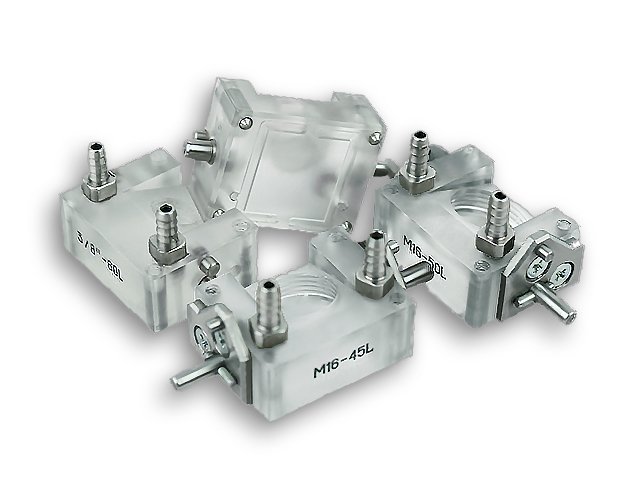
TOFD wedges specification:
| Catalog number | Refracted angleo |
| WS45 L-3/8"-TOFD | 45 |
| WS50 L-3/8"-TOFD | 50 |
| WS60 L-3/8"-TOFD | 60 |
| * WS70 L-3/8"-TOFD | 70 |
| WS45 L-M16-TOFD | 45 |
| WS50 L-M16-TOFD | 50 |
| WS60 L-M16-TOFD | 60 |
| WS70 L-M16-TOFD | 70 |
* included in basic supply kit
| Testing object parameters | |
| Thicknesses | .25 - 2 in (6 - 50 mm) |
| Diameter for cylindrical objects | from 12 in (300 mm) to flat |
| Diameter for spherical objects | from 33 ft (10 m) to flat |
| Profile types | any |
| Scanner (with all electronics onboard) | |
| Dimensions (L×W×H) | 380×310×240 mm |
| Weight | 7,5 kg |
| Number of TOFD pairs | 1 |
| Coupling liquid supply | individually for each probe |
| Compatible probes and wedges | |
| Frequencies | 1-15 MHz |
| Angles (L-wave) | 45°, 60°, 70° |
| Measurement | |
| Number of cursors | 2 |
| Types of cursors | Conventional (cross) Hyperbolic |
| Manual positioning | ✔ |
| Automatic positioning | ✔ |
| Absolute measurements | ✔ |
| Relative measurements | ✔ |
| Indications table | ✔ |
| Indications parameters | X, X1, X2, dX Z, Z1, Z2, dZ Type (Point, Top, Bottom, Middle) Amplitude |
| Units | mm / in / us |
| Output fields | 5 |
| Unit connectors | |
| Pulser and Receiver | 2 × BNC |
| Encoder | ✔ |
| Power | ✔ |
| RS485 | ✔ |
| LAN | ✔ |
| Sync input | ✔ |
| Trigger output | ✔ |
| Pulser | |
| Types | Spike + SWP |
| Voltage (SWP) | 50 V, 100 V, 150 V, 200 V, 250 V, 300 V, 400 V |
| Energy (SWP) | 20 ns to 1000 ns with 10 ns step Manual & Auto modes |
| Voltage (Spike) | Low: 50 V, High: 300 V |
| Damping | ✔ |
| PRF | from 15 to 6000 Hz |
| Receiver | |
| Range | Up to 100 us |
| Delay | Up to 100 us |
| Gain | 0 to 110 dB, with 0.1 dB step |
| Max signal input | 20 V p-p |
| Bandwidth | 0.2 MHz - 27 MHz |
| Filters | 1 MHz, 2-3 MHz, 4-5 MHz, 10 MHz, 15 MHz, Full band |
| Rectification | Full Wave |
| Signal Average | 2x / 4x / 8x / 16x / 32x |
Basic supply kit:
- TOFD 2.2 PRO scanner (with electronics, battery and transducers on board);
- Software for MS Windows notebook/tablet;
- Charger;
- Manual guide (hard copy);
- Hard case.
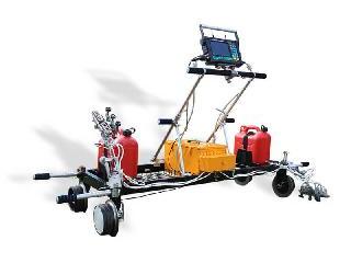
Available at option:
- Rugged Notebook or Tablet PC with pre-installed TOFD Software;
- Additional transducers (see tab "Transducers");
- Portable water tank (3,52gal/16l) with motorized pump (2-4,5Bar);
- Extra battery.